

1 Selecting of a building element
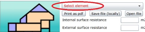
The desired building element can be selected from the drop-down list, so that the external and internal surface heat transfer resistance is automatically determined. The default surface resistance values are given in accordance with standard EN ISO 6946. The values of the surface resistances can also be freely selected and modified by the user. Surface resistance refers to surfaces that are in direct contact with the air and affect the U-value of the external building envelope. The surface resistance depends on the direction of the heat flow, the temperature of the surface, the emissivity of the surface and, in the case of external surfaces, the wind speed. The surface temperatures, emission values and wind speeds used in the calculator are based on the default values specified in standard EN ISO 6946. Individual surface resistance can be calculated using the surface resistance calculator.
2 Setting the properties of the layers
2.1 Selecting the material

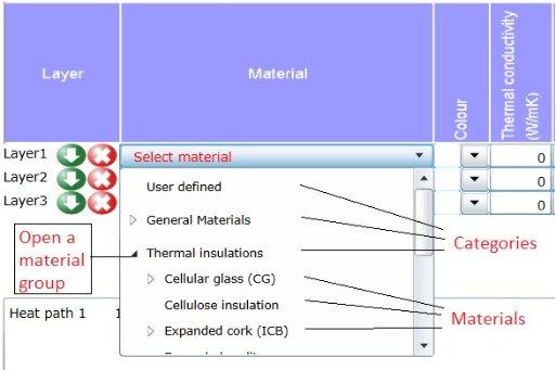
Select a material from the drop-down menu for the first layer. The thermal conductivity value is also automatically shown for the selected material, but this can be changed freely. If you want to choose a material that is not on the list, select the "User defined" option. In this case, the thermal conductivity factor must be specified individually by the user.
There are three groups:
- General materials
- Thermal insulations
Here basic types of thermal insulation materials can be found. The displayed thermal conductivity values are typical values and are suitable for someone to perform a general calculation. The thermal conductivity value of a certain type and brand of thermal insulation material can be obtained from the manufacturer of the product. It is important to use the design value of the thermal conductivity, which is derived from the declared value, which is determined from the 90/90 characteristic value. To determine the design value, the declared value may need to be modified in accordance with standard EN ISO 10456, taking into account temperature, humidity and aging factors.
- Air layers
The thermal resistance of the air layers depends on the direction of the heat flow, the thickness of the air layer, the emissivity of the surfaces in contact with the air layer, and the degree of ventilation of the air gap. Most of the building materials have a high emissivity, so for an air gap that is bounded by common building materials, choose the high emissivity option (High-E). A low-emission surface is, for example, a thermal insulation material which is faced with aluminium foil towards the air layer. The given thermal resistance values refer to the case when the air layer is not ventilated (in the case of vertical air layers, e.g. walls, the surface of the ventilation openings is less than 500 mm2 per horizontal running meter, and in the case of horizontal air layers, e.g. roofs, less than 500 mm2 / m2 of roof surface). If the air layer is "well ventilated" (in the case of vertical air layers, e.g. walls, the surface of the ventilation openings is greater than 1500 mm2 per horizontal running meter, or in the case of horizontal air layers, e.g. roofs, greater than 1500 mm2 / m2 roof surface), then the air layer and all other layers between the air layer and the external environment must be neglected during the calculation.
2.2 Thickness
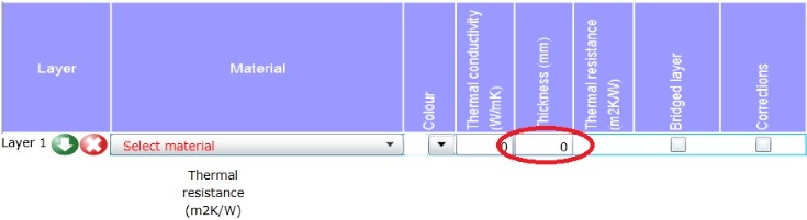
Enter the layer thickness in millimeters. When the thickness is entered, a schematic diagram of the layer order appears in the upper right corner.
2.3 Colour
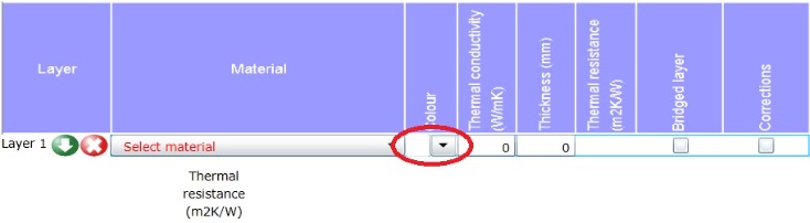
During material selection, the layer appears with a default color. The color can be modified using the color palette, which can be displayed by scrolling down the arrow next to the thermal conductivity.
2.4 Thermal bridges
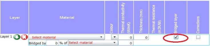
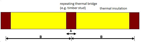
Check the box if the layer has a thermal bridge. It means a repetitive thermal bridge, which is repeated with a fixed distance in the entire external building envelope. When the box is checked, another line appears where the percentage of the thermal bridge and the thermal conductivity of its material can be set. The percentage (%) must be given as the ratio A / B shown in the figure below, where parameter A is the width of the thermal bridge and parameter B is the center distance of the repeating thermal bridge.
Explanatory diagram for a thermal bridged layer:
2.5 Corrections
Tick the checkbox if a correction is required. When the box is ticked, a new line will appear so that corrections caused by fasteners or air gaps can be made.
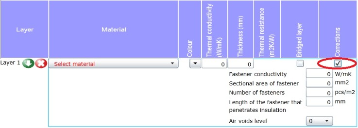
Corrections due to fasteners:
If fasteners of metallic material penetrate the insulation layer, a correction is required. The thermal conductivity of the fastener, the cross-sectional area, the length of the fastener that penetrates the thermal insulation material and the number of fasteners per square metre must be given.
Corrections due to air gaps:
Where air gaps may occur in the thermal insulation layer (e.g. in the case of rigid insulation boards with high dimensional tolerance), a correction may be required. EN ISO 6946 distinguishes between three different levels. Level 0 can be chosen if there are no air gaps that would have a significant effect on the thermal resistance. Level 1 can be selected if there is a through air gap between the cold and hot sides of the insulation but no airflow, and level 2 should be selected if there is a risk of airflow between the cold and hot sides.
3 Inserting a new layer

Click on the icon to insert a new layer under an existing layer. There is no limit on the number of layers you can insert.
4 Deleting a layer

Click on the icon to delete the layer.
5 Restart
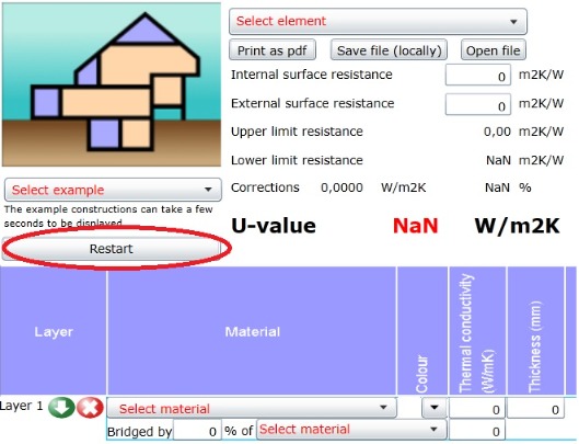
Click this button to start a new calculation.
6 Examples
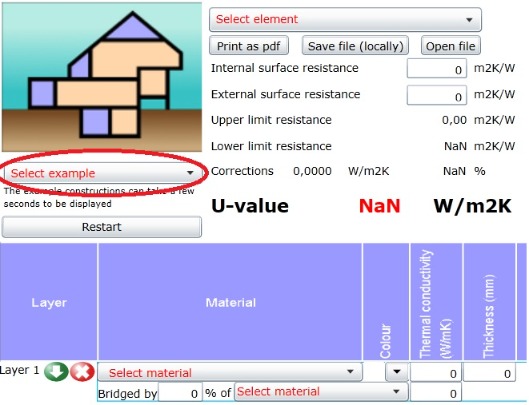
Use this drop-down menu to choose from different example calculations.
7 U-value
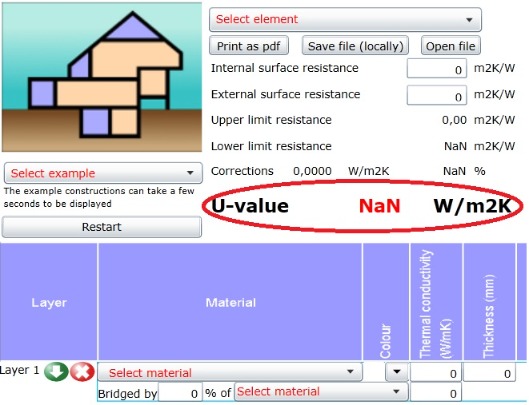
The U-value of the building element is recalculated and displayed as soon as a parameter changes. If a parameter is missing or the calculation cannot be performed (e.g. division by 0), the NaN term is displayed.
8 Print to PDF and save and load layers
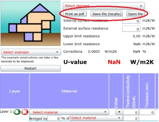
The PDF/print button opens the browser print dialog. From there, the calculation can be printed directly or saved as a PDF file.
The "Save construction" button saves the compiled layer build-up as a text (.txt) file. The browser allows you to choose the file name and save location.
The "Open" button can be used to reload a previously saved construction. The save format remains compatible with earlier saved files, so previously stored constructions can still be used.
9 Slab-on-ground floor
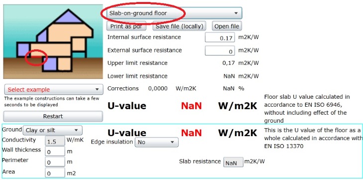
The U-value of floors lying on the ground is calculated in accordance with EN ISO 13370.
In addition to the layer data, additional data is required:
- soil and its thermal conductivity, which can be selected from the drop-down menu
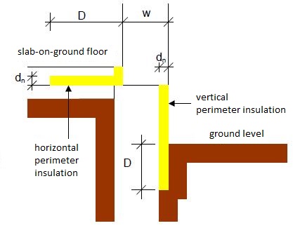
- thickness of the external wall element in metres (w) (see figure)
- perimeter of the slab-on-ground floor, the total edge length along which the floor is in contact with a wall adjacent to an external space or unheated space
- the total area of the slab-on-ground floor
- where an additional perimeter thermal insulation is provided in the horizontal ground floor or in the plinth wall, the thermal conductivity and the thickness (dn) and width (D) of this perimeter thermal insulation shall be given
- thermal resistance of the slab-on-ground floor, this is calculated automatically by the calculator by entering the layer order (this is the thermal resistance in accordance with EN ISO 6946)
10 Suspended ground floor
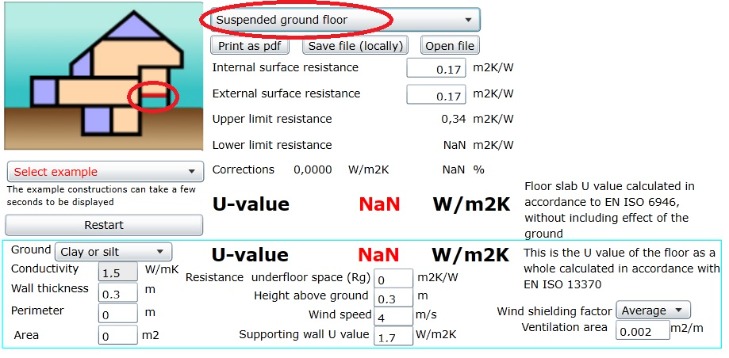
The calculation of the U-value of suspended ground floors is carried out in accordance with EN ISO 13370.
In addition to the layer data, additional data is required:
- soil and its thermal conductivity, which can be selected from the drop-down menu
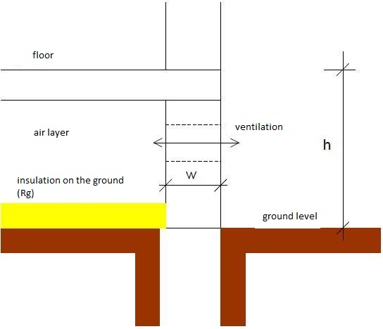
- the thickness (w) of the above-ground plinth wall closing the air layer, in metres (see figure)
- the perimeter of the floor, the total edge length along which the floor is in contact with a wall adjacent to an external space or unheated space
- the total area of the floor
- if a thermal insulation layer is placed on the ground surface under the ventilated air layer, the thermal resistance of the insulation layer (Rg) must be given
- height above ground level, expressed in metres, which is the distance between the ground level and the upper plane of the ground floor (h)
- wind speed, which is the average wind speed at 10 m height, expressed in m/s
- U-value of the above ground plinth wall closing the air layer, calculated in accordance with EN ISO 6946
- wind shading factor, which may be sheltered (e.g. city centre), average (e.g. suburbs) or exposed (e.g. rural environment)
- ventilation area, which is the area of ventilation openings per linear metre in m2
11 Basement floor
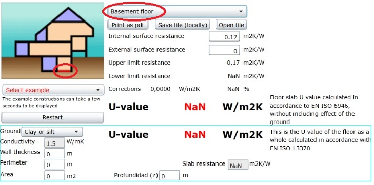
The calculation of the U-value of the basement floor is carried out in accordance with EN ISO 13370.
In addition to the layer data, additional data is required:
- soil and its thermal conductivity, which can be selected from the drop-down menu
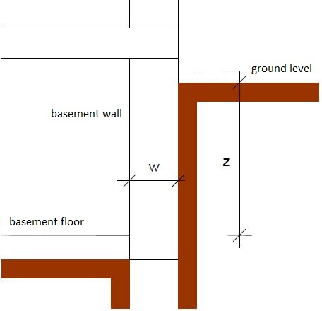
- total thickness of the basement wall (w) in metres (see figure)
- basement floor perimeter, the total edge length along which the basement floor is in contact with the wall adjacent to the external space or unheated space
- the total area of the basement floor in question
- the thermal resistance of the basement floor - this is calculated automatically by the calculator by entering the layers (resistance in accordance with EN ISO 6946)
- depth (z) in metres, which is the distance between the ground level and the upper plane of the basement floor
12 Basement wall
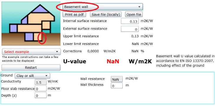
The U-value of basement walls is calculated in accordance with EN ISO 13370.
In addition to the layer data, additional data is required:
- soil and its thermal conductivity, which can be selected from the drop-down menu
- thermal resistance of the basement floor calculated in accordance with EN ISO 6946 (this must be calculated beforehand, see basement floor calculation)
- depth (z) in metres, which is the distance between the ground level and the upper plane of the basement floor (see figure above)
- thermal resistance of the basement wall - this is calculated automatically by the calculator by entering the layer orders
- total thickness of the basement wall (w) in metres.